
Detroit Diesel Mechanical Unit Injection Systems Service & Calibration Guide
Instant Answer & Quick Specs Box
Engineering Overview & Technical Coverage
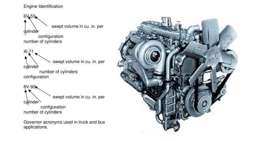
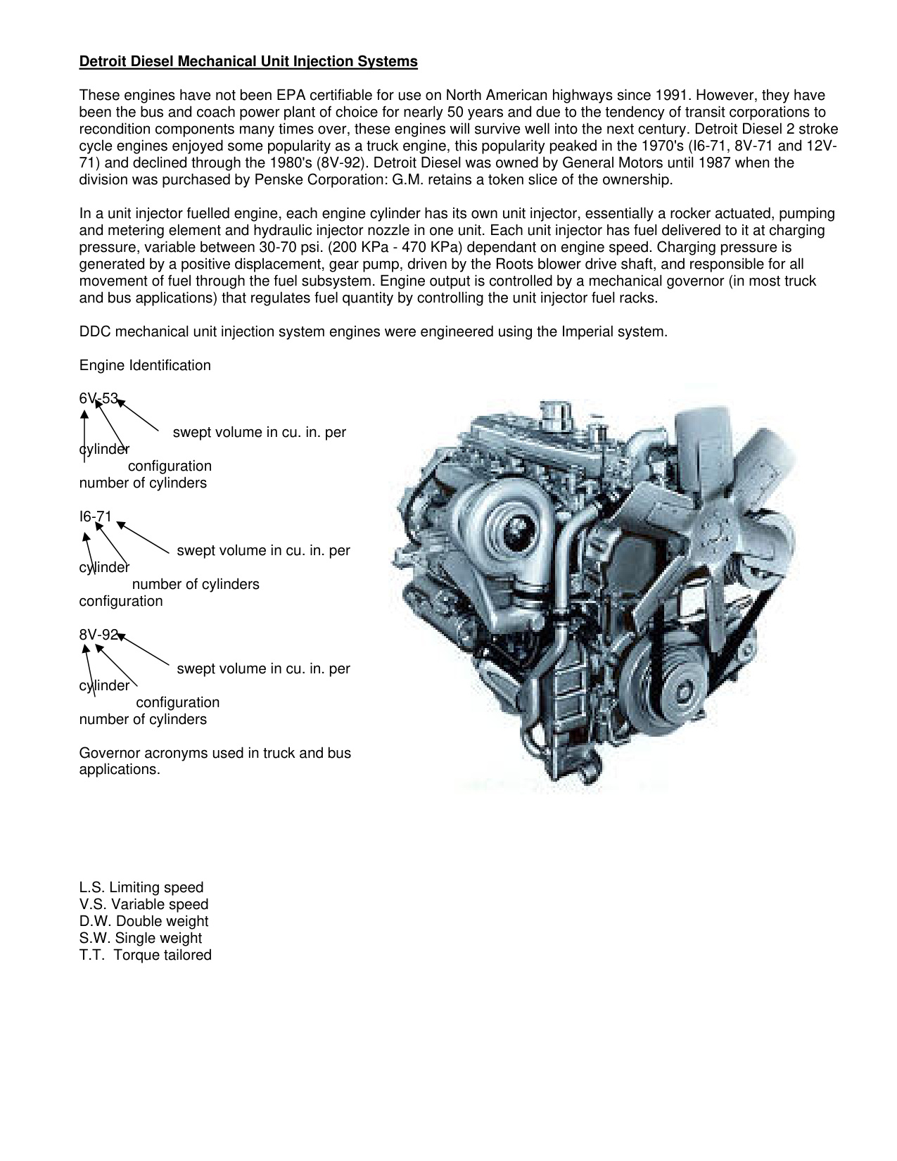
Detroit Diesel two-cycle diesel engines (Series 53, Series 71, and Series 92) rely on precision Mechanical Unit Injectors (MUI) that combine the high-pressure pumping element and atomizing spray nozzle into a single compact unit. Driven directly from the overhead camshaft via rocker arms and push rods, unit injectors eliminate external high-pressure fuel lines and potential pulse lag. This specialized factory technical guide covers injector identification, plunger and bushing helix metering, governor control rack synchronization, and timing gage calibration.
Critical Engineering Specifications & Tightening Sequence
| Component / Adjustment | Engine Family | Torque / Clearance Limit | Service Procedure & Notes |
|---|---|---|---|
| Injector Hold-Down Clamp Bolt | 53, 71, 92 Series | 20 – 25 lb-ft (27 – 34 N·m) | Hold clamp square while torquing to avoid cocking the injector body |
| Fuel Jumper Pipe Flare Nuts | All MUI Injectors | 130 – 160 lb-in (15 – 18 N·m) | Do not overtighten fuel manifold connectors; verify O-ring integrity |
| Injector Timing Dimension | Series 53 / 71 / 92 | Gage Height (1.460″ – 1.484″) | Use Detroit Diesel precision push rod timing gage in follower hole |
| Control Rack Free Travel | Governor Linkage | Zero Binding Across Full Stroke | Ensure all injector control rack levers move smoothly without drag |
| Spill Deflector & Seal | Cylinder Head Well | Copper Sealing Washer | Always install a new copper washer under the injector body nut |
Complete Service Chapter Directory
- 1. Main Fuel System Architecture: Primary/secondary filter placement, positive displacement fuel pump, restricted return fitting (orifice), and fuel gallery routing.
- 2. Unit Injector Design & Operation: Sectional blueprints of plunger, upper/lower metering ports, helical control edges, check valve, and multi-hole spray tip.
- 3. Injector Identification & Output Classes: Identification tags (Crown vs. Needle valve), output delivery volume charts, and replacement guidelines.
- 4. Governor Linkage & Rack Positioning: Adjusting governor control rods, injector rack lever set screws, and synchronizing all cylinders to identical fuel delivery.
- 5. Injector Timing Procedure: Dialing in plunger follower height with official Detroit Diesel pin timing gages before setting idle speed.
- 6. Diagnostic Troubleshooting: Isolating misfiring cylinders, black smoke caused by stuck racks, fuel dilution from spill pipe leaks, and aeration testing.
Heavy Equipment Mechanics: Free Interactive Calculation Suite
Calculate fastener stretch, torque unit conversions (Nm to ft-lbs), engine displacement, and compression ratio online in seconds:
Open Diesel Mechanic Calculators →Frequently Asked Questions
What is the hold-down clamp bolt torque for Detroit Diesel unit injectors?
The injector clamp bolt on Detroit Diesel Series 53, 71, and 92 engines must be torqued to 20 – 25 lb-ft (27 – 34 N·m) while ensuring the clamp remains centered and level.
How do I know if a unit injector control rack is sticking?
Disconnect the governor operating rod and move the injector control tube by hand. If any resistance, binding, or hesitation is felt, loosen the individual rack levers one by one to isolate the sticking injector.
